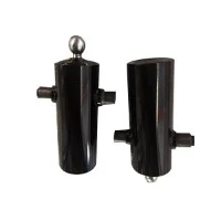
Latest Products
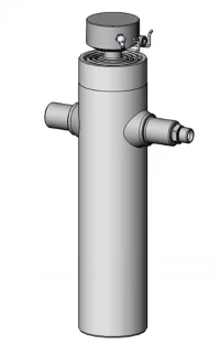
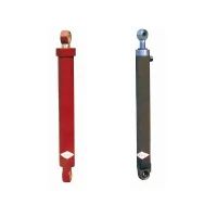


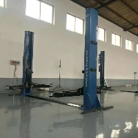
Contact Us
- Xingshi West Road, Wenfeng Subdistrict, Laizhou City, Shandong, P. R. China
- sales@lztonghesheng.com

Lift Table Hydraulic Cylinders
Lift table hydraulic cylinders provide compact, high-tonnage vertical motion for scissor lifts, material handling platforms, dock levelers, and industrial positioning systems. Built to withstand high side-load conditions, mechanical deflection, and high-duty operational cycles, these double-acting and single-acting welded cylinders ensure reliable platform stability under heavy eccentric loads.
Description
Tonghesheng Machinery is one of the competitive manufacturers and suppliers of high-quality lift table hydraulic cylinders, and we are also equipped with a professional factory, welcome to buy lift table hydraulic cylinders products from our company.
Lift table hydraulic cylinders provide compact, high-tonnage vertical motion for scissor lifts, material handling platforms, dock levelers, and industrial positioning systems. Built to withstand high side-load conditions, mechanical deflection, and high-duty operational cycles, these double-acting and single-acting welded cylinders ensure reliable platform stability under heavy eccentric loads.
Engineered with high-yield strength steel tubes and precision-ground, hard-chrome-plated piston rods, these cylinders integrate velocity fuses, anti-drift check valves, and internal cushioning. This design eliminates platform drift, sudden collapse hazards, and hard mechanical stops during continuous production operations.
Key Specifications
|
Parameter |
Range / Options |
Testing / Compliance Standard |
|
Bore Size |
40 mm – 250 mm (1.5" – 10") |
ISO 3320 / DIN 24334 |
|
Rod Diameter |
25 mm – 180 mm (1.0" – 7.0") |
Precision ground to Ra 0.2 µm |
|
Stroke Length |
Up to 3,000 mm (118") |
Stroke tolerance ±1.0 mm |
|
Operating Pressure |
Rated: 16 – 25 MPa (2,300 – 3,600 PSI) Peak: 31.5 MPa (4,500 PSI) |
Hydrostatic proof tested at 1.5× working pressure |
|
Cylinder Barrel Material |
ST52-3 / E355 / 20# Seamless Steel Tube |
Honed finish internal roughness Ra ≤ 0.4 µm |
|
Piston Rod Material |
42CrMo4 / C45 (1045) Steel |
Chrome layer thickness 25–50 µm; Surface hardness HRC 55–60 |
|
Sealing System |
Hallite / Parker / NOK polyurethane U-cups, PTFE step seals, guide rings |
Temp range: -30°C to +110°C (-22°F to +230°F) |
|
Mounting Options |
Cross-tube, spherical ear bearings, clevis, flange, trunnion |
Machined to ISO mounting tolerances |
|
Fluid Compatibility |
Mineral-based hydraulic oil (HM/HV ISO VG 32, 46, 68), water-glycol |
ISO 4406 cleanliness code ≤ 18/16/13 |
Key Product Features
High-Load Mechanical Stability: Heavy-wall ST52-3 honed tubing prevents barrel expansion and seal bypass under high shock load spikes during scissor lift acceleration and stop cycles.
Eccentric Side-Load Resistance: Extended wide-span bronze guide sleeves and wear rings absorb lateral forces generated by scissor leg pivot angles and off-center platform loads.
Integrated Safety & Anti-Drift Systems: Threaded valve ports accept direct-mounted hose-burst check valves (velocity fuses) and counter-balance valves to lock fluid in the cylinder chamber if a hydraulic line fails.
Low Stick-Slip Seals: Custom PTFE step seals and high-durometer polyurethane rod seals deliver smooth low-speed extension, preventing platform shuddering under max capacity.
Corrosion Resistance: Rods pass a minimum 96-hour NSS (Neutral Salt Spray) test per ISO 9227 (optional 200+ hour rating available for wet or chemical environments).
Lifting Mechanism Design Considerations
Integrators and machine builders sizing hydraulic cylinders for scissor lift tables must account for varying mechanical leverage ratios throughout the lift cycle:
Initial Breakaway & High Mechanical Leverage
When the scissor arms are collapsed, the cylinder operates at a sharp angle relative to the frame. The effective torque arm is minimal, requiring peak force from the cylinder to start upward movement. Cylinder bore sizing must be calculated against starting mechanical advantage rather than mid-stroke push force.
Buckling Resistance & Stroke Length
Long-stroke cylinders in single-stage or high-reach multi-stage lifts experience compression loads that risk Euler column buckling. Piston rod diameter must be selected based on the total extended length and maximum column force at full vertical extension.
Stroke End Cushioning & Deceleration
Plunging heavy platform loads without speed control creates fluid pressure spikes and mechanical impact at full stroke end. Adjustable hydraulic cushions absorb kinetic energy in the last 15–20 mm of travel, reducing stress on pivot pins and structural welds.
Typical Applications
Scissor Lift Tables: Material handling tables, work-positioning platforms, and ergonomic assembly stations.
Dock Levelers & Pit Lifts: Loading dock ramps and vehicle maintenance platform lifts.
Automated Guided Vehicle (AGV) Lifts: Low-profile vertical hydraulic modules built into warehouse mobile robotics.
Freight & Pallet Elevators: Heavy vertical transportation lifts linking mezzanine floors in distribution centers.
Stage & Theatre Platforms: Smooth, low-noise scissor platforms requiring exact level alignment and zero drift.
Customization Options
|
Category |
Available Customizations & Specifications |
|
Port Integration |
SAE J514 Flange, BSPP, NPT threads, or direct-mounted integrated manifold blocks |
|
Rod Protection |
Hard nickel-chrome plating, quenched & tempered steel, or flexible bellows covers |
|
Mounting Configurations |
Spherical ear bearings, heavy-duty clevis, cross-tube, or trunnion mounts |
|
Integrated Sensors |
Internal magnetostrictive linear position sensors or inductive proximity switches |
|
Surface Finish |
Multi-layer epoxy paint (C3–C5 ISO 12944 anti-corrosion rating) or QPQ nitriding |
Manufacturing Process
Step 1: Raw Material Inspection
High-grade seamless steel tubes (ST52-3/E355) and alloy round bars (42CrMo4) undergo ultrasonic flaw detection and chemical composition analysis upon arrival.
Step 2: Precision Barrel Processing
Tubes undergo skiving and roller burnishing to produce a high-precision internal surface finish (Ra ≤ 0.4 µm), maintaining strict circularity and wall thickness tolerances.
Step 3: Piston Rod Machining & Hardening
Alloy steel rods undergo CNC precision turning, induction hardening (HRC 55–60), and micro-cracked hard chrome electroplating (minimum 25 µm layer).
Step 4: Robotic Welding & Precision Assembly
End caps, cross-tubes, and flanges are welded using automated MIG/MAG robotic welding units. Assembly takes place in a dust-free cleanroom using pre-calibrated torque tools.
Inspection and Testing
Every lift table cylinder undergoes rigorous inspection before shipment to ensure compliance with specified pressure ratings and leak-free performance:
100% Hydrostatic Pressure Test: Tested at 1.5 times the maximum working pressure.
Internal Bypass / Seal Leakage Test: Extended pressure-hold testing in fully extended and retracted positions to ensure zero internal drift.
Dimension & Concentricity Verification: CMM and laser micrometer inspection of pin center-to-center dimensions, mounting parallelism, and port alignment.
Surface Roughness & Coating Thickness: Ultrasonic gauge verification of hard chrome plating depth and surface finish profilometer testing.
Cleanliness Protocol: Internal fluid flushing to ISO 4406 oil cleanliness standard ≤ 18/16/13.
What Buyers Should Provide for a Quotation
To receive an accurate technical quotation and 3D CAD model within 24–48 hours, please provide the following design parameters:
- Bore Diameter & Rod Diameter (or target push force at operating pressure)
- Stroke Length & Extended/Retracted Pin-to-Pin Distance
- Maximum Working Pressure (bar / PSI)
- Mounting Configuration (e.g., cross-tube, clevis, spherical bearing) with pin hole diameters
- Port Type & Location (SAE, BSPP, NPT, or integrated valve block interface)
- Operating Environment (temperature range, indoor/outdoor exposure, chemical contact)
- Expected Annual Quantity & Project Timeline
FAQ
Q: What cylinder features prevent a lift table from dropping if a hydraulic hose bursts?
A: Direct-mounted hose-burst valves (velocity fuses) or counter-balance check valves are integrated into the cylinder port. If flow exceeds the rated threshold due to a broken line, the valve locks hydraulic fluid inside the barrel, instantly stopping platform descent.
Q: How do you prevent internal leakage and platform drift over long holding periods?
A: Platform drift is minimized through high-precision honing (Ra ≤ 0.4 µm) combined with zero-leakage PTFE step seals and polyurethane U-cups backed by elastomeric O-rings. Static pressure testing ensures the cylinder holds positions without measurable pressure drop.
Q: Can you design custom stroke cushions for high-speed lift platforms?
A: Yes. Progressive mechanical cushioning can be integrated at both rod end and cap end positions. These internal cushions restrict hydraulic return flow during the last 15–20 mm of travel, decelerating heavy loads smoothly without external shock absorbers.
Q: What is the standard lead time for custom production orders?
A: Standard prototypes and customized sample cylinders are typically completed within 3 to 4 weeks. Full batch production orders generally ship within 4 to 6 weeks, depending on material specifications and order volume.
Q: Are 3D CAD files provided prior to manufacturing approval?
A: Yes. Detailed 3D CAD files (STEP, IGES) and 2D dimensional approval drawings are supplied alongside every formal engineering proposal for customer sign-off before production begins.
Hot Tags: lift table hydraulic cylinders China, manufacturers, suppliers, factory, company, high-quality, buy, products, Heavy Duty Double Acting Hydraulic Cylinder, Heavy Duty Welded Hydraulic Cylinder, High Pressure Extrusion Press Hydraulic Cylinder, High Pressure Hydraulic Test Cylinder, Loader Welded Hydraulic Cylinder, Welded Hydraulic Cylinder for Agricultural Equipment
You Might Also Like