Latest Products


Contact Us
- Xingshi West Road, Wenfeng Subdistrict, Laizhou City, Shandong, P. R. China
- sales@lztonghesheng.com
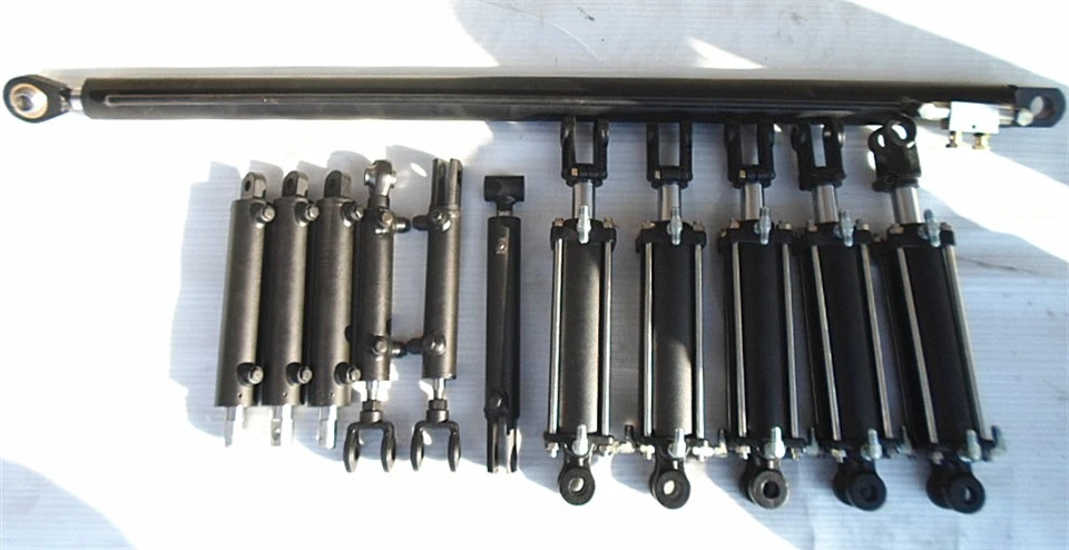
Underbody Tipping Hydraulic Cylinders
Underbody tipping hydraulic cylinders are compact, multi-stage telescopic actuators installed directly beneath the dump body or trailer bed. Designed specifically for low-clearance chassis configurations, these cylinders convert hydraulic fluid energy into linear thrust to lift loads during tipping operations.
Description
Tonghesheng Machinery is one of the competitive manufacturers and suppliers of high-quality underbody tipping hydraulic cylinders, and we are also equipped with a professional factory, welcome to buy underbody tipping hydraulic cylinders products from our company.
Underbody tipping hydraulic cylinders are compact, multi-stage telescopic actuators installed directly beneath the dump body or trailer bed. Designed specifically for low-clearance chassis configurations, these cylinders convert hydraulic fluid energy into linear thrust to lift loads during tipping operations.
Unlike front-end tipping cylinders that mount on the front cabin wall, underbody cylinders fit within the chassis frame rail height. This position maintains a low center of gravity for the vehicle while preserving cargo space behind the cab. These cylinders are available in single-acting (gravity load-retracted) and double-acting (hydraulic-retracted) multi-stage configurations, with custom stroke lengths and stage counts tailored to specific payload capacities and vehicle frame dimensions.
Key Specifications
|
Parameter |
Standard Range / Specification |
Notes / Options |
|
Number of Stages |
2 to 5 stages |
Depends on required stroke and retracted length |
|
Stage Diameters |
O.D. 60 mm to O.D. 220 mm |
Customized per thrust calculation |
|
Maximum Operating Pressure |
16 MPa to 22 MPa (160 bar to 220 bar) |
Rated for heavy-duty tipping cycles |
|
Test Pressure |
24 MPa to 30 MPa |
100% factory hydrostatic test |
|
Stroke Length |
400 mm to 4,000 mm |
Configured to vehicle dump angle requirement |
|
Lifting Capacity |
3 Tons to 45 Tons |
Determined by geometry and operating pressure |
|
Operating Temperature |
-30 deg C to +100 deg C |
Standard nitrile; Viton seals for higher temp |
|
Seamless Tube Material |
27SiMn / ST52 / E355 |
Cold-drawn, stress-relieved seamless steel |
|
Tube Wall Honing Precision |
Inner surface roughness Ra <= 0.4 um |
H8/H9 dimensional tolerance |
|
Stage Surface Plating |
Hard Chrome Coating (25 um to 50 um thickness) |
Micro-hardness >= 850 HV; Salt spray test >= 96 hrs |
|
Mounting Types |
Bottom trunnion, cross-tube, top spherical eye |
Bushings or greaseable bearings available |
|
Hydraulic Fluid Compatibility |
ISO VG 32 / VG 46 mineral oil |
Synthetic fluid compatible seals available |
Key Product Features
Cold-Drawn 27SiMn Alloy Steel Tubing
Stage barrels are produced using cold-drawn 27SiMn seamless steel tubes. Compared to standard carbon steels like Q235 or ST37, 27SiMn yields higher tensile strength (>= 980 MPa) and yield strength (>= 835 MPa). This material strength allows thinner tube walls without sacrificing burst pressure limits, directly reducing total cylinder dead weight and increasing payload headroom.
Precision Honing and Hard Chrome Surface Treatment
Inner tube walls undergo precision honing to achieve an internal surface finish of Ra <= 0.4 um, protecting internal piston guide rings from premature wear. The outer diameters of each telescopic stage are ground and plated with hard chrome (minimum thickness 25 um, option for 50 um). Plated surfaces achieve a surface hardness of >= 850 HV, resisting impact from flying gravel and preventing corrosion in outdoor operating environments.
Integrated Sealing System
Each stage utilizes a multi-lip sealing arrangement consisting of a primary polyurethane (PU) step seal, a secondary U-cup seal, and an external skeleton wiper seal. This combination limits bypass leaks during high-pressure lifting while keeping dirt, mud, and washdown water out of internal cavities. Guide bands made of filled PTFE prevent metal-to-metal contact between stages under high side-load forces.
Low-Profile Compact Structure
The multi-stage nested design allows a retracted length that fits within tight chassis depths (as low as 350 mm to 500 mm). This permits installation directly over the rear axle assembly or middle frame cross-members without raising the vehicle's unladen deck height.
Tipping System Design Considerations
Installing an underbody cylinder requires careful mechanical and hydraulic calculation to avoid premature mechanical failure, frame twisting, or rod buckling.
1. Mechanical Advantage and Mechanical Geometry
Unlike front-end cylinders where the lifting point is far from the pivot hinge, underbody cylinders attach closer to the bed's pivot axis.
Required Force Formula:
F = (W * L_cg) / (L_cyl * sin(Theta))
F: Required cylinder lifting push force
W: Total load weight (payload + body weight)
L_cg: Distance from bed pivot hinge to payload center of gravity
L_cyl: Distance from bed pivot hinge to cylinder mounting pin
Theta: Angle between cylinder axis and load bed plane
Because L_cyl is shorter than total bed length, the cylinder initial stage must handle significantly higher push force than the payload itself.
2. Side Load and Buckling Resistance
When a vehicle tips on uneven ground or loaded unevenly, lateral forces act upon the fully extended telescopic stages.
Underbody cylinders experience high bending moments due to their mounting angle and proximity to the chassis.
Internal guide rings must be spaced to maintain overlap at full extension. Stage overlap lengths are calculated at a minimum ratio of 1.2 to 1.5 times the outer tube diameter to absorb bending stresses without galling the inner walls.
3. Hydraulic Flow Rate and Retraction Control
Extension Speed: High oil flow from the pump during early extension stages produces rapid movement as stage diameters decrease. Flow control valves or proportional pump controls prevent violent acceleration changes as the system transitions between stages.
Lowering Risk: Single-acting underbody cylinders rely on body weight to retract. If oil flow during retraction is unrestricted, vacuum pockets can form in the upper cylinder stages, leading to air ingress and stage sticking. Counterbalance valves or flow-restrictor cartridges maintain positive backpressure during descent.
Typical Applications
Three-Way Tip Trucks (3-Way Tippers): Vehicles designed to unload cargo from the left, right, or rear. Underbody cylinders mounted on a central gimbal or spherical trunnion socket allow multi-directional angular movement during operation.
Light to Medium Commercial Dump Trucks (3.5T to 18T GVW): Municipal service trucks, sand and gravel delivery vehicles, and urban maintenance tippers requiring a low loading height.
Agricultural Tipping Trailers: Farm trailers carrying grain, silage, or fertilizers where the tow vehicle's hydraulic system drives the cylinder at standard operating pressures (16 MPa to 20 MPa).
Hook-Lift and Skip Loader Auxiliary Systems: Secondary tipping frames or container positioners requiring compact, high-force linear actuators within subframes.
Customization Options
Custom engineering options based on vehicle chassis geometry and operating specifications:
Mounting Interface Options
Bottom Spherical Eye with Greasable Bushings
Mid-Trunnion / Cross-Tube Mounts
Top Ball Socket / Spherical Clevis (essential for 3-way tipper movement)
Port Configuration
Standard BSPP (G thread) or SAE O-ring boss ports
Custom port angles and manifold integration directly on the base cap
Surface Protection Options
Standard alkyd primer paint
High-durability polyurethane finish coat (custom RAL colors)
Salt spray protection options: Nickel-Chrome plating or Salt-Bath Nitriding (QPQ) for extreme corrosive environments
Integrated Valve Options
Built-in end-of-stroke hydraulic knock-off valves to cut fluid supply automatically at maximum tip angle
Velocity fuses (hose-burst protection valves) mounted directly into the cylinder inlet port
Manufacturing Process
[ Raw Material Input ] --> [ CNC Machining & Turning ] --> [ Precision Honing ]
↓
[ Assembly & Packaging ] <-- [ Painting Line ] <-- [ Hydrostatic Test ] <-- [ Robotic Welding ]
Raw Material Inspection: Ultrasonic testing on incoming 27SiMn seamless steel tubes to verify wall thickness uniformity and confirm zero internal material flaws.
CNC Turning and Boring: Machining stage stop rings, seal grooves, and end caps on multi-axis CNC lathes to guarantee tight geometric tolerances (IT7 to IT8).
Inner Tube Honing: Deep-hole honing of stage bores to achieve Ra <= 0.4 um roughness and exact roundness tolerances.
Outer Diameter Grinding and Plating: Precision cylindrical grinding followed by electroplating with hard chrome, then polished to a mirror finish (Ra <= 0.2 um).
Robotic Welding: Automated MIG/MAG welding of end caps, bottom trunnions, and oil ports under controlled shield gas mix (80% Ar / 20% CO2) to ensure weld penetration and zero porosity.
Clean Room Assembly: Assembly of seals, guide rings, and telescoping stages inside a dust-controlled assembly bay to prevent contaminant entrapment.
Inspection and Testing
Every manufactured unit undergoes quality control prior to shipment:
|
Test Item |
Test Pressure / Method |
Acceptance Standard |
|
Hydrostatic Proof Test |
1.5x Rated Pressure |
Zero pressure drop over 5 minutes |
|
Internal Leakage Test |
Rated Working Pressure |
Zero oil bypass across stages |
|
External Leakage Test |
Rated Working Pressure |
Zero fluid seepage past seals |
|
Full-Stroke Motion Test |
Full Extension Cycle |
Smooth stage movement, no binding |
|
Chrome Plating Thickness |
Electromagnetic Gauge |
Minimum 25 um across rod length |
|
Salt Spray Corrosion |
ASTM B117 Neutral |
Rating 9+ after 96 to 240 hours |
100% Factory Pressure Testing: Every cylinder undergoes full extension and retraction cycles at test pressure (up to 30 MPa) on automated test benches.
Oil Cleanliness Control: Testing fluid filtered to ISO 4406 18/16/13 standard to guarantee clean internal cavities upon delivery.
What Buyers Should Provide for a Quotation
To receive a technical quotation and dimensional drawing within 24 hours, provide the following parameters:
Dump Body Specifications:
Total payload weight + body tare weight (Tons)
Internal bed length, width, and height (mm)
Required maximum tipping angle (e.g., 45 deg, 50 deg)
Installation Envelope Dimensions:
Maximum allowable retracted cylinder length (L_min)
Distance from bed pivot hinge to cylinder mounting axis
Available space height beneath the chassis deck
Hydraulic System Operating Parameters:
System max working pressure (MPa or Bar)
Pump delivery flow rate (L/min)
Cylinder type: Single-acting or Double-acting
Mounting Requirements:
Preferred top connection (e.g., ball socket, pin eye)
Preferred bottom connection (e.g., trunnion, cross tube)
Pin diameters and bush material requirements
FAQ
Q: What is the primary operational difference between underbody and front-end tipping cylinders?
A: Underbody cylinders install beneath the load bed closer to the rear pivot point, requiring higher hydraulic thrust to lift the payload compared to front-end cylinders. However, underbody units preserve space behind the driver cabin, lower the total chassis center of gravity, and enable three-way tipping functionality (left, right, and rear unloading).
Q: Why is 27SiMn steel preferred over standard ST52 or 1045 steel for telescopic stages?
A: 27SiMn is a low-alloy structural steel with higher yield strength (>= 835 MPa after heat treatment). This enables thinner stage wall thickness while maintaining structural rigidity and burst pressure safety margins, resulting in a lighter cylinder weight without sacrificing load capacity.
Q: How do you prevent stage sticking or uneven extension during operation?
A: Stage sequencing and smooth extension are achieved through precision internal hydraulic porting and strict diameter tolerances. Correct guide ring clearance combined with polished inner hone finishes prevents stick-slip behavior under load.
Q: Can these underbody cylinders be used for 3-way side-tipping trucks?
A: Yes. For 3-way tipping applications, cylinders are configured with top ball-and-socket mounts and bottom spherical trunnions. This ball-joint articulation allows the cylinder to swivel laterally without introducing twisting forces to the piston stages or seals.
Q: What is your standard production lead time and quality warranty policy?
A: Standard lead time for custom batch orders is 30 to 40 days following drawing approval. All products include a 12-month quality warranty against manufacturing defects, seal failures, or structural weld faults under normal operating conditions.
Hot Tags: underbody tipping hydraulic cylinders China, manufacturers, suppliers, factory, company, high-quality, buy, products, Power Extension and Retraction Telescopic Cylinder, Road Milling Machine Hydraulic Cylinder, Telescopic Dump Truck Hoist Cylinder, Telescopic Hydraulic Cylinder for Lifting Equipment, Trunnion Mounted Single Acting Telescopic Cylinder, Wear Resistant Mining Hydraulic Cylinder
You Might Also Like